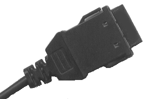
Step 4- Changing the cable of the Psion 5/5MXThe standard cable
supplied by Psion (PsiWin cable) has a DB9-pin connector. The DB9 doesnīt have to be
modified because all wires of the DB9-connector are connected to the "Honda"
connector which fits into the rear side of the Psion.
Not all of the wires (a total of 9) are used.
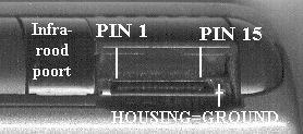
Measurements showed me, that pinnumber 1 of the Honda-connector is connected to the
connector on the left side of the Psion: which is the external power supply.

|
 |
The "Honda"-connector |
Rear side of the Psion 5/5MX |
For PC-systems pin 9 is assigned "Ring Indicator", which means
that if a modem is connected, the pc "knows" when a call is coming in. Because
this function (auto answer) is rarely used by 5mx users, pin 9 seems to be the ideal one
to use for another purpose. In other words: if the cable is modified to supply the 5/MX
with external power, the modem will not "auto answer" an incoming call. As far
as I know no other functions will be affected by the modification.
It is very attractive to use pin 9 of the DB9-connector for the external power supply.
So the modification is very simple: take a sharp hobby-knife and cut the rear side of the
Honda connector carefully in two pieces (horizontal direction). Within the connector are
parts wich can easily be disassembled. The replace wire from pin 6 to pin 1 (also see the
table mentioned below).
Original pin assignment
| Honda |
1 |
2 |
3 |
4 |
5 |
6 |
7 |
8 |
9 |
10 |
11 |
12 |
13 |
14 |
15 |
| D-connector |
- |
8 |
6 |
2 |
4 |
9 |
7 |
3 |
- |
- |
- |
- |
- |
- |
5 |
| Function |
- |
CTS |
DSR |
RXD |
DTR |
NU |
RTS |
TXD |
|
- |
- |
- |
- |
- |
GRND |
NU = Not Used by Psion. Pin 1 of the DB9-connector is not
connected
Modified pin assignment
| Honda |
1 |
2 |
3 |
4 |
5 |
6 |
7 |
8 |
9 |
10 |
11 |
12 |
13 |
14 |
15 |
| D-connector |
9 |
8 |
6 |
2 |
4 |
- |
7 |
3 |
- |
- |
- |
- |
- |
- |
5 |
| Function |
POWER |
CTS |
DSR |
RXD |
DTR |
- |
RTS |
TXD |
|
- |
- |
- |
- |
- |
GRND |
Power = Only power input, see the warning below.
Connect pin 15 with the metal case of the Honda connector too.
ATTENTION: So far no defects have been reported. But anyway:
- I tried this modification on the series 5 and series 5MX. There is no guarantee that the
modification will work on other (Psion) systems too.
- It is very important the cuts are made very cautious. If some of the wires are damaged
and make contact with other wires, this may result in a short circuit. A short circuit
between the power supply and a data wire may result in internal damage of the Psion.
- Donīt use any other pin assignments than indicated. You may damage the Psion, but also
the other connected devices.
- Donīt forget to place a fuse between the powerbox and your motorbike (200 mA).
- Always check if there is a voltage on pin 1 of the Honda connector, if there is an
external power supply connected to the original connector on the left side of the Psion.
If this is true (unexpected!) then Iīll advise you to use this cable only for
GPS-navigation purposes. Mark the cable if necessary, to prevent you from mixing up the
different cables.
|
![]()