Step 2 & 3- The stabelized Power SupplyIf you don´t want to
change the batteries of the GPS and Psion continuously, or come to the conclusion on the
middle of a very busy crossing that the batteries are completely drained, it would be wise
to connect an external power supply to the units. But the system can work without the
external power supply too.
This power supply has to be of a good quality, to prevent the GPS and Psion from any
(electrical) internal damage.
That´s why I chose a power supply which is stabilized, from Velleman. These sets from Velleman seem very reliable to me and
anybody can solder / assemble them together. The used power supply fits (after a bit of
sawing) into a standard component box with the dimensions of 100 x 50 x 25mm. This way it
stays a compact unit, for which you can always find a place on your bike.
I chose Velleman, but I´m sure there are other suppliers too. The local electronics shop
will advice you.
 
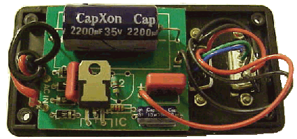
Power supply mounted on the lid of the
component box, together with the 2 pieces DB9-connectors. |
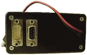
The other side of the lid: The left
connector is meant for the Psion, the right one for the GPS. The black/red cable goes to
your battery of the motorbike. Be sure that you mount a fuse between the box and the
battery (200mA). |
The output of the power supply, the single red (+) wire, is
connected to the pinnumbers 9 of both connectors. The single black wire is connected to
both pinnumbers 5 and the cases of the DB9-connectors.
The power supply has been adapted for this job. Normally there will be an
adjustable resistence mounted on the circuitboard. Because of the possible vibrations of
the motorbike and / or car, I replaced the adjustable one with a fixed one. This is shown
on the left side picture above next to "2". The fixed resistance will prevent
internal damage because of a changed value and thus another power output then meant.
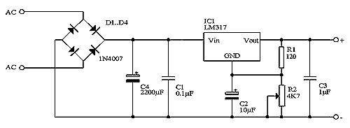
By the diagram:

is R2 the adjustable resistance. Because R1 has a resistance of 120 Ohm, and the output
voltage has to be 6 Volts, there will be 4,8 Volts over R2 (see the site of Velleman). With a simple calculation you´ll know
that you have to take a resistance for R2 = 480 Ohm. In practice the value of R2 can vary
just a little bit.
Important
- The output of the power supply has to be between +5,95 and +6,10 Volts.
- Before you connect any device, check the output first.
- Use a good voltmeter for the final check, to prevent the device from damage.
- Use as input voltage (AC) for testing a high(er) DC voltage first. E.g. two serial
connected 9 Volts batteries, which will supply +18 Volts then. So always check the output
voltage with an input voltage of at least +18 Volts. Inverse the AC-connection (switch the
+ and - of the batteries, so the input will be -18 Volts) and check the output again. If
the the output always stays exactly +6 VDC, then you may connect the GPS and Psion
devices.
|
![]()