| Step 1- The connection cable from the de
Garmin GPS12XL to power supply
You can buy these cables in the shop, or on the internet (see links). With a little bit of patience itṀs nice to make this cable
yourself.
The housing of the GPS12XL has been made of plastic (ABS?) just a few materials will
stick on. You can use this point.
- Take a cotton bud, and put some paste on the contactpoints and the walls of the
Garming-connector side. This paste should not interfere with ABS and should be cleaned
with water. Example of a good paste is silicone-grease, or toothpaste (which I used).
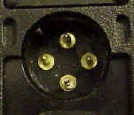
- Take a plastic bag (sandwich bag) and push it well into the opening, so the pins will
pierce through the plastic bag. Now the wall of the GPS-unit is protected against sticky
materials.
- Put on the four pins a connector ment for circuits-boards. Solder the wires to the
connectors.
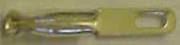 (real dimensions
approx. 15*2mm) (real dimensions
approx. 15*2mm)
- Take an empty case of a 25-pole D-connector and drill a hole in it with the size of the
connectorhole in the GPS
- Put one half of the D-connector case (the one whith the hole) on the GPS-unit and fill
everything well with a 2-component paste. You can obtain this paste in a hobby-market.
- Put the screws on the second half of the D-connector and let it all become hard.
The result you get, will look like this:
Now you have to connect the new connector with the DB9- connector, according to the
table below.
Note: Use shielded cables only. Connect one side of the
DB9-connector with pin 5 (Ground) and the case of the connector. This is to reduce the
chance of (electrical) disturbances caused by the motorbike.
GPS
side |
C
A
B
L
E |
Powerbox side |
|
Pin assignment
(DB9-connector female to cable)
|
Pin assignment of the Garmin connection
(the connector is thus itṀs mirror image!)
|
Pin assingment of the DB9-connector
- (not used)
- DATA FROM PC/PSION - white
- DATA TO PC/PSION - brown
- (not used)
- GROUND - black
- (not used)
- (not used)
- (not used)
- POWER - red
Connect the case of the connector with Pin 5 (ground) and with the
shield of the cable too. |
|